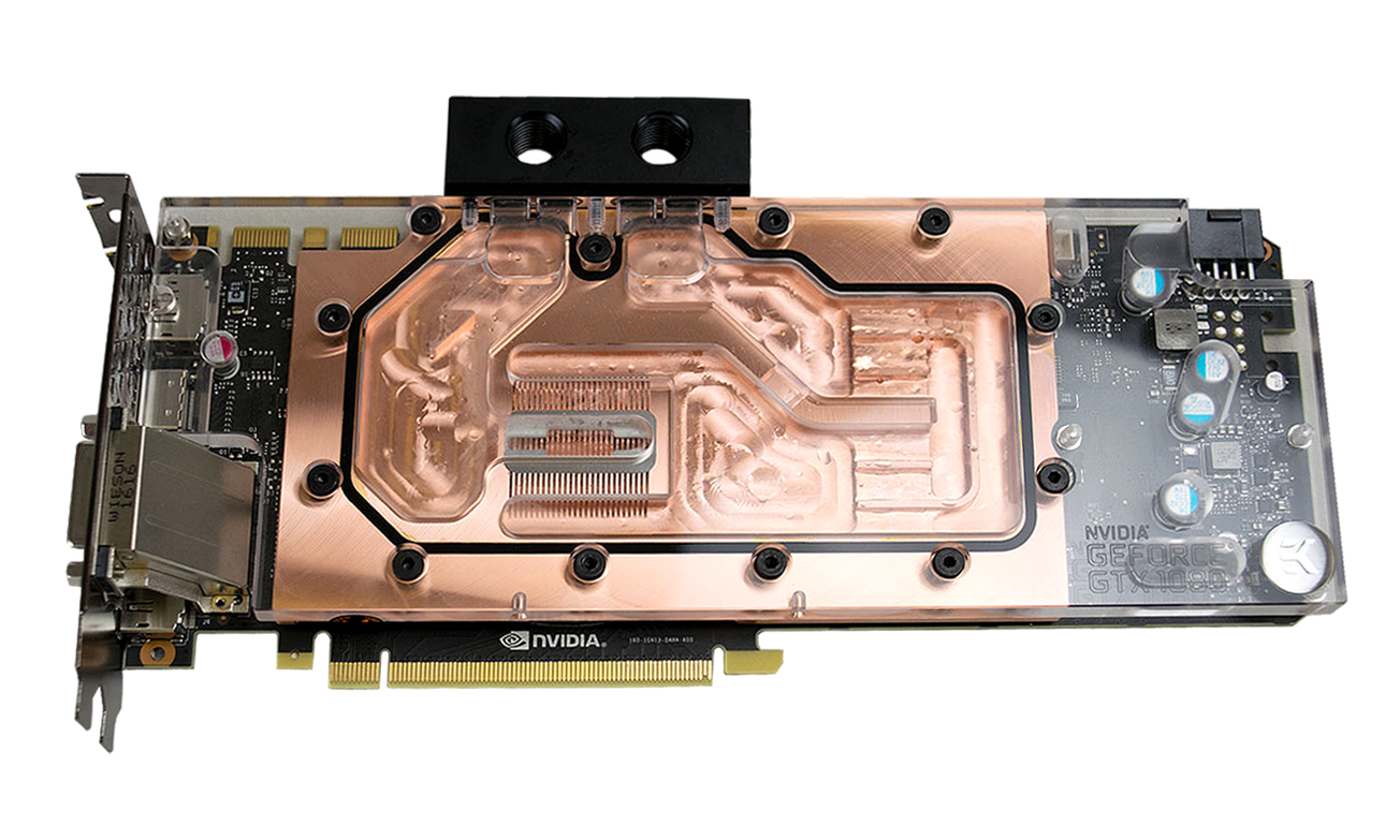
How To Install A Waterblock On Nvidia's GTX 1080
In the last few years, water cooling computer hardware has become a much more popular choice among enthusiasts. You often had to improvise to make things fit in the early days of water cooling, and you almost certainly risked voiding your warranty by replacing your GPU’s stock cooling solution. Those days are mostly behind us now. Many graphics card makers, including MSI, Asus and EVGA, have embraced water cooling as a viable alternative for enthusiasts. These companies often still honor warranty coverage after installing a water block, provided you return the card with the proper stock heat sink. These companies have even gone so far as to work directly with EK Water Blocks to build properly supported cooling blocks.
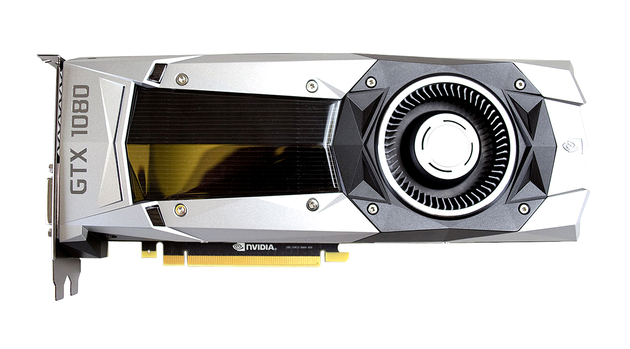
There’s no question that a proper full-cover water block can offer dramatic cooling performance improvements. The only real question is how hard is it to install a fancy full-cover water block on a modern GPU? To answer that question, we decided to try it for ourselves with Nvidia’s new top dog, the GeForce GTX 1080 Founder’s Edition.
Before we start, it should be noted that this isn’t our test sample. A friend of mine happened to be one of the lucky few people to actually get their hands on a retail Founder’s Edition model in the first week of release. He subsequently followed that purchase up with an EK-FC1080 GTX full-cover water block with the clear acrylic top and copper base. He was kind enough to let us document the installation process and share the results.
Preparation
Before you start disassembling your brand new expensive graphics card,you’re going to want to make sure you have all the necessary tools and parts for the job. First and foremost, you obviously need the graphics card and a matching water block. Not all graphics cards have custom water blocks, so make sure you verify that before you purchase either part. EK Water blocks offer an excellent resource called the cooling configurator that will help cross reference its products with all of the graphics cards on the market.
In addition to the hardware you’ll need a couple of fairly basic, though not necessarily common, tools. Each graphics card will likely have slightly different screw sizes, so make sure you have a universal toolkit on hand with several bit sizes. The Founder’s Edition card required a PH2 Phillips head screwdriver and a tiny #4 socket. You’ll also need some isopropyl alcohol to clean up the thermal paste off of the GPU. You can get away with an 80 percent concentration, but the higher the percentage, the quicker the alcohol evaporates. You’ll also need a microfiber cloth to wipe the thermal paste off of the GPU and a pair of scissors for the thermal pads.
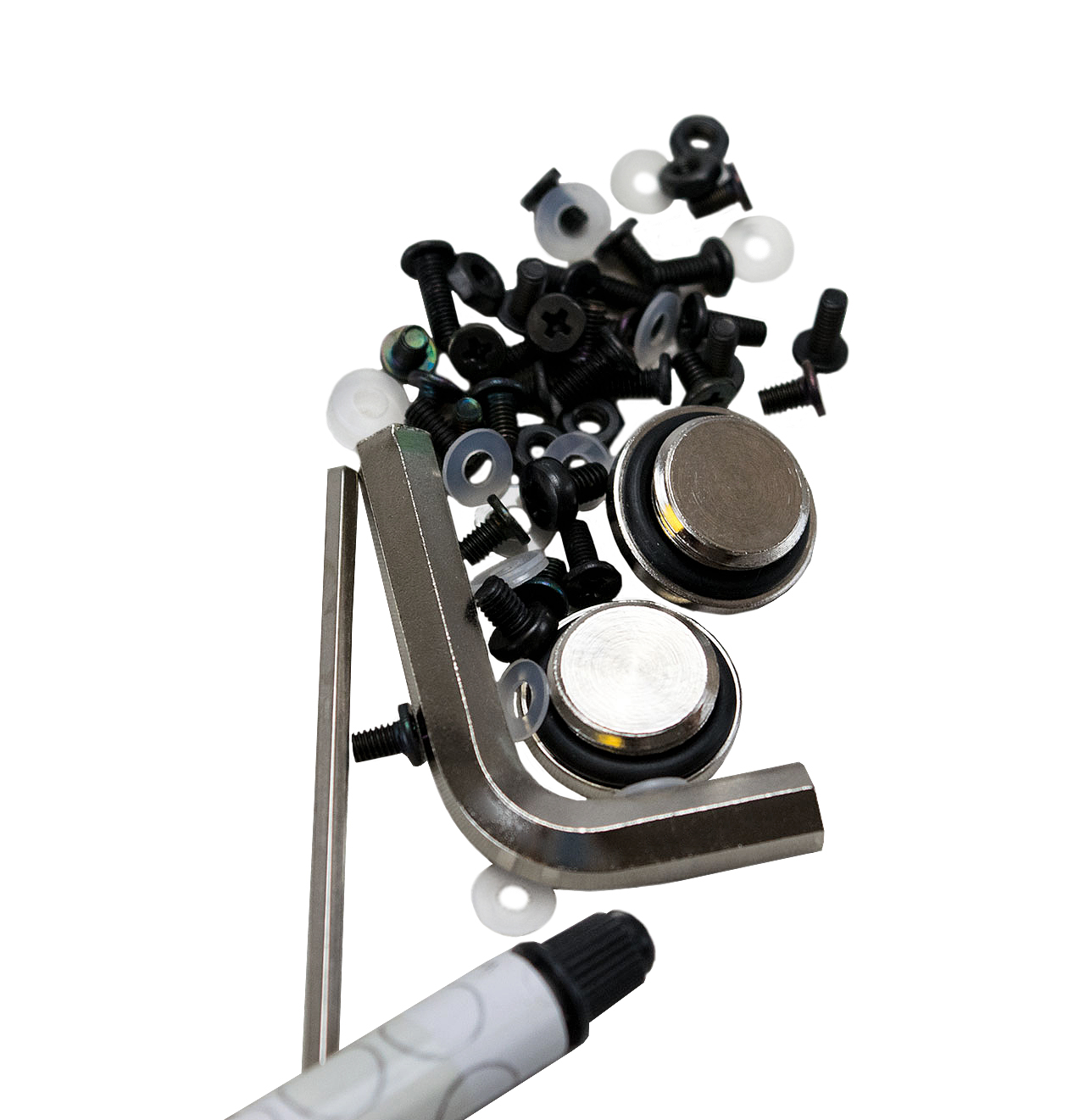
Everything else you need should be in the bag of parts in the box that comes with the water block. EK provides all of the screws that you need to install the block, and thermal interface material to apply onto the GPU. The kit also includes thermal pads for the VRMs and memory modules.
Many Screws To Remove
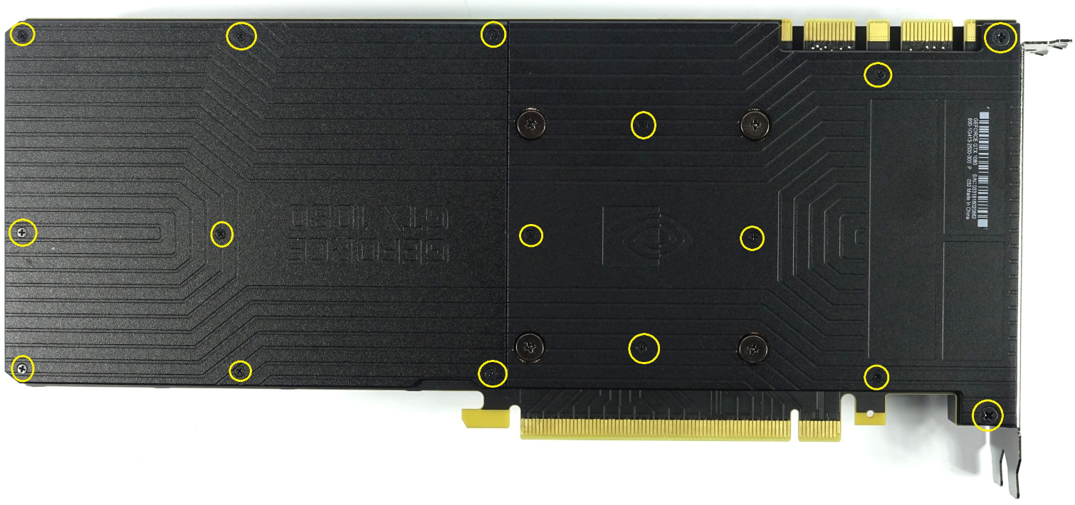
You begin by removing the backplate, which then allows you to remove the heatsink and fan assembly from the GeForce GTX 1080 Founder’s Edition. The 10-series Founder’s Edition is the first Nvidia reference card to include a backplate, but this one doesn’t help cool the card. In fact, the company said that you should remove part of it if you run SLI with these cards. The backplate is actually two independent parts.
Get Tom's Hardware's best news and in-depth reviews, straight to your inbox.
The rear section of the backplate is secured with eight absolutely tiny screws. We didn’t damage any of ours while removing them, but we’ve heard stories of people snapping the heads off of these screws. Be very gentle with them, and make sure you don’t turn the screwdriver the wrong way. The front half of the backplate has six of those tiny screws. You must also remove two larger screws next to the I/O bracket. You can ignore the four large screws that surround the GPU; the backplate slides off right over those. You’ll want to save those for last, as they are the spring loaded screws that hold tension over the GPU.
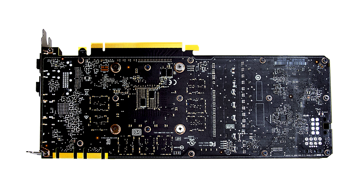
Once you’ve removed the backplate, you’ll notice that there are hex head screws where each of the backplate retention screws were. The hexes have small threaded holes where the retention screws mount, which is why the #4 socket is necessary. You could probably use pliers if you really needed too, but I wouldn’t recommend risking scratching the PCB. The socket head screws are also very tiny. We didn’t break any while disassembling the card, so we can’t say how resilient they are, but you’d be wise to be gentle with these screws, too.
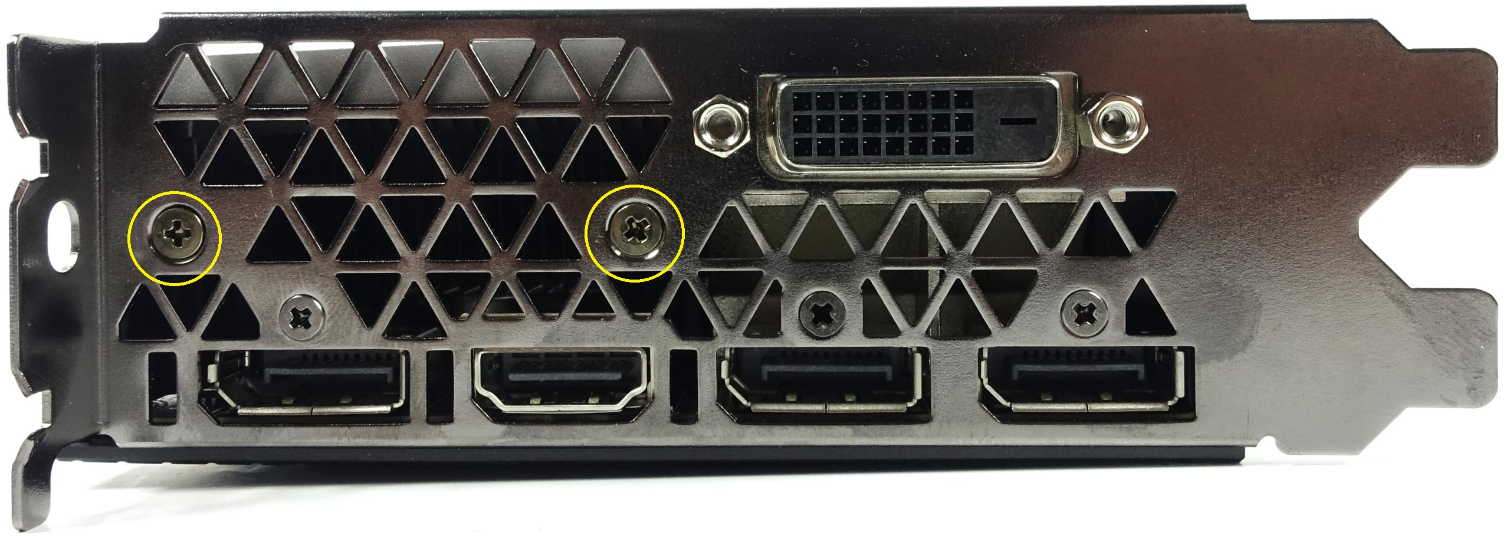
There are two Phillips head screws that you must remove from the I/O bracket. Don’t worry about the three smaller ones; they don’t have any bearing on the heatsink removal, but the larger ones have to go. Finally, remove the four large spring loaded screws holding the block tight against the GPU.
Be Gentle
Now that you have removed all of the screws that hold the cooling solution in place, you can peel the heatsink assembly away from the PCB. Be careful not to pull too fast and too hard, as there are a couple of cables you’ll have to disconnect.
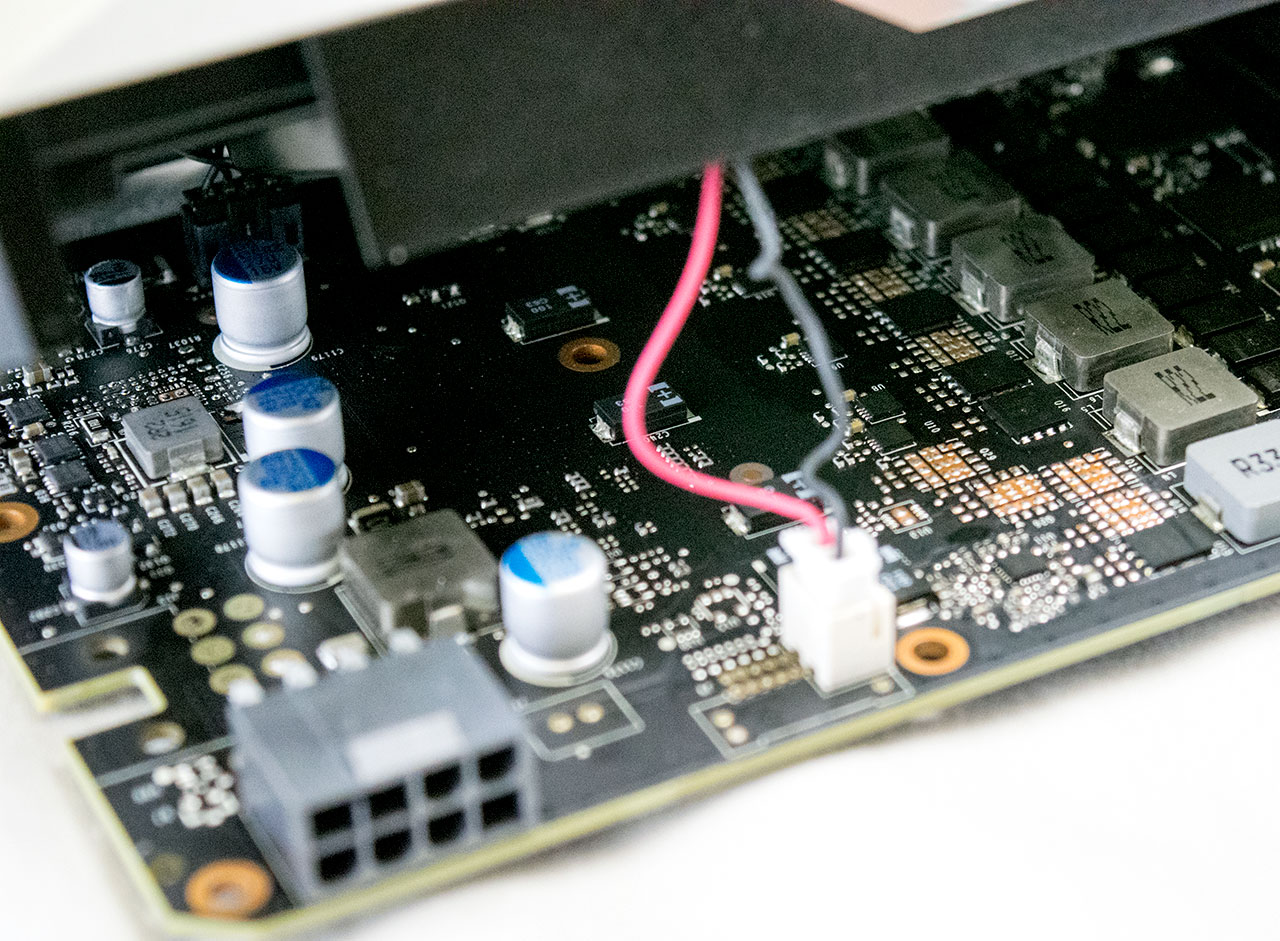
You’ll find a small white plug next to the 8-pin power connector. Gently disconnect the plug. You may need some needle nose pliers to do this, but we were able to remove it by hand. Whatever you do, don’t tug on the cables; pull the plug itself.
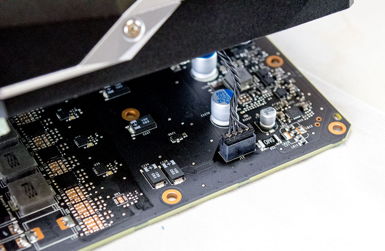
You’ll find the second plug on the bottom edge of the card, almost directly below the white plug. This one has four black cables going to it. We found that this plug was tighter in the socket than the white one, but again we were able to disconnect it by hand.
With then two cables properly disconnected you can pull the heatsink and fan assembly off of the card. The entire assembly comes off as one, including the memory cooling plate.
Pro Tip: Once you have the heatsink removed, reinstall all of the retention screws into it so that you don’t lose any of them.
Cleanup
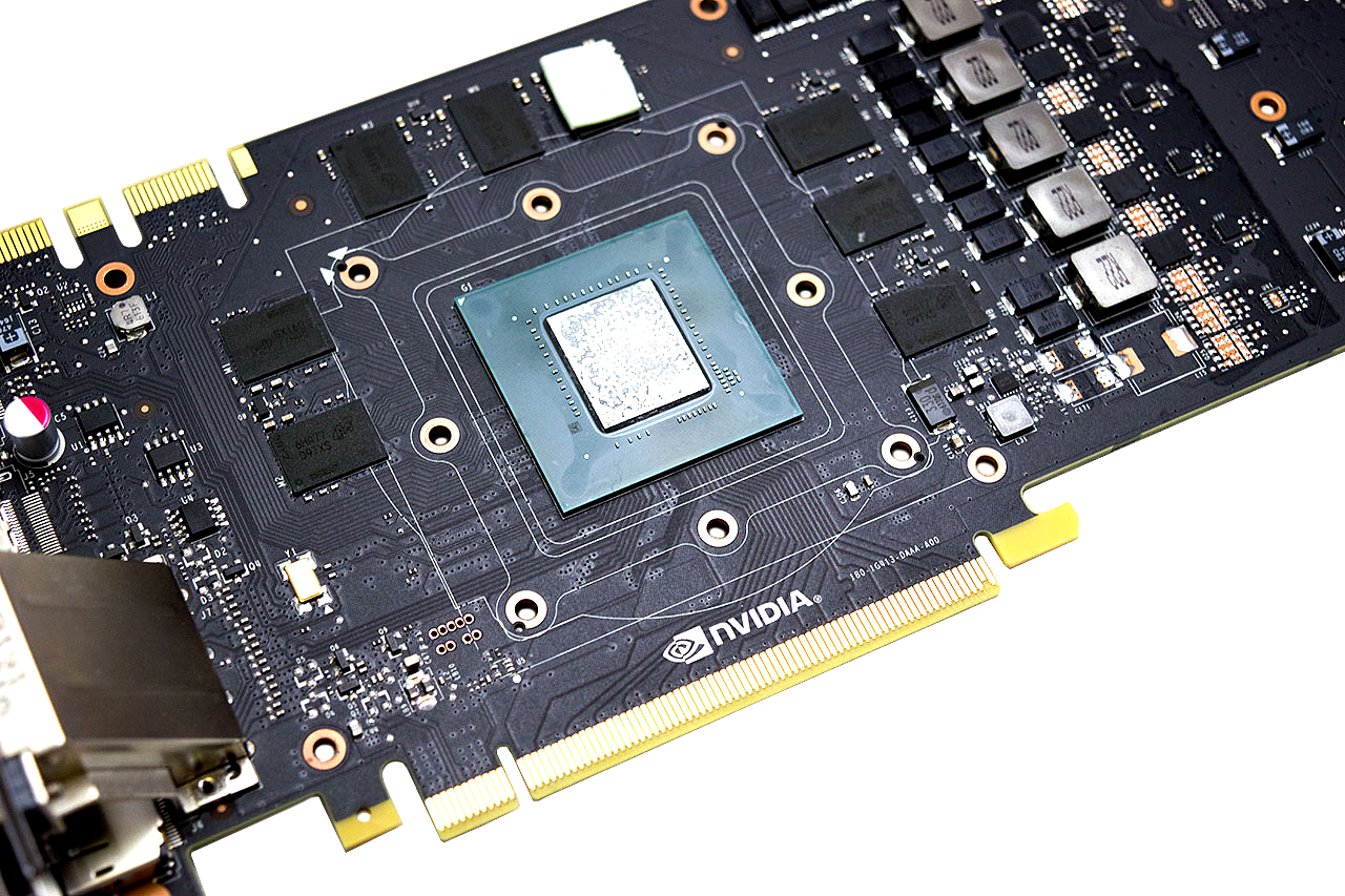
You’ll want to tidy up the contact surface of the GPU before installing the water block. It’s also a good idea to clean off the memory chips, voltage modules, and MOSFETs while you’re at it. You may find that some of the chips have thermal pads on them still. Make sure you save these (attach them to the heatsink) because you’ll need them if you ever have to send the graphics card in for warranty, or if you ever plan to sell it to someone else.
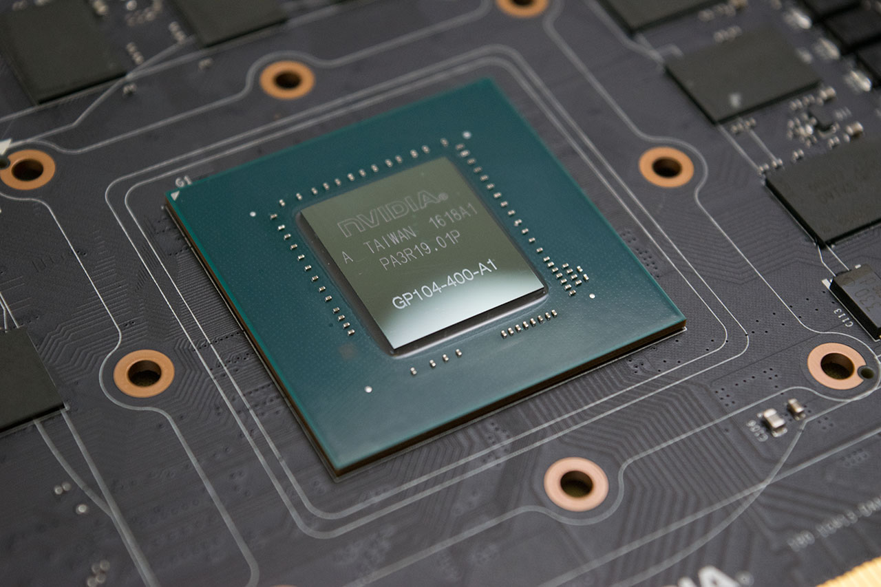
To clean the components, take your microfiber rag and pour some isopropyl onto it. You don’t need to soak the fabric fully, just make sure it's damp to the touch. Carefully wipe down the GPU surface to remove the old thermal paste. The GPU should glisten in the light when you are done cleaning it. You don’t have to be as thorough with the other components, though. You just need to make sure they are clear of debris.
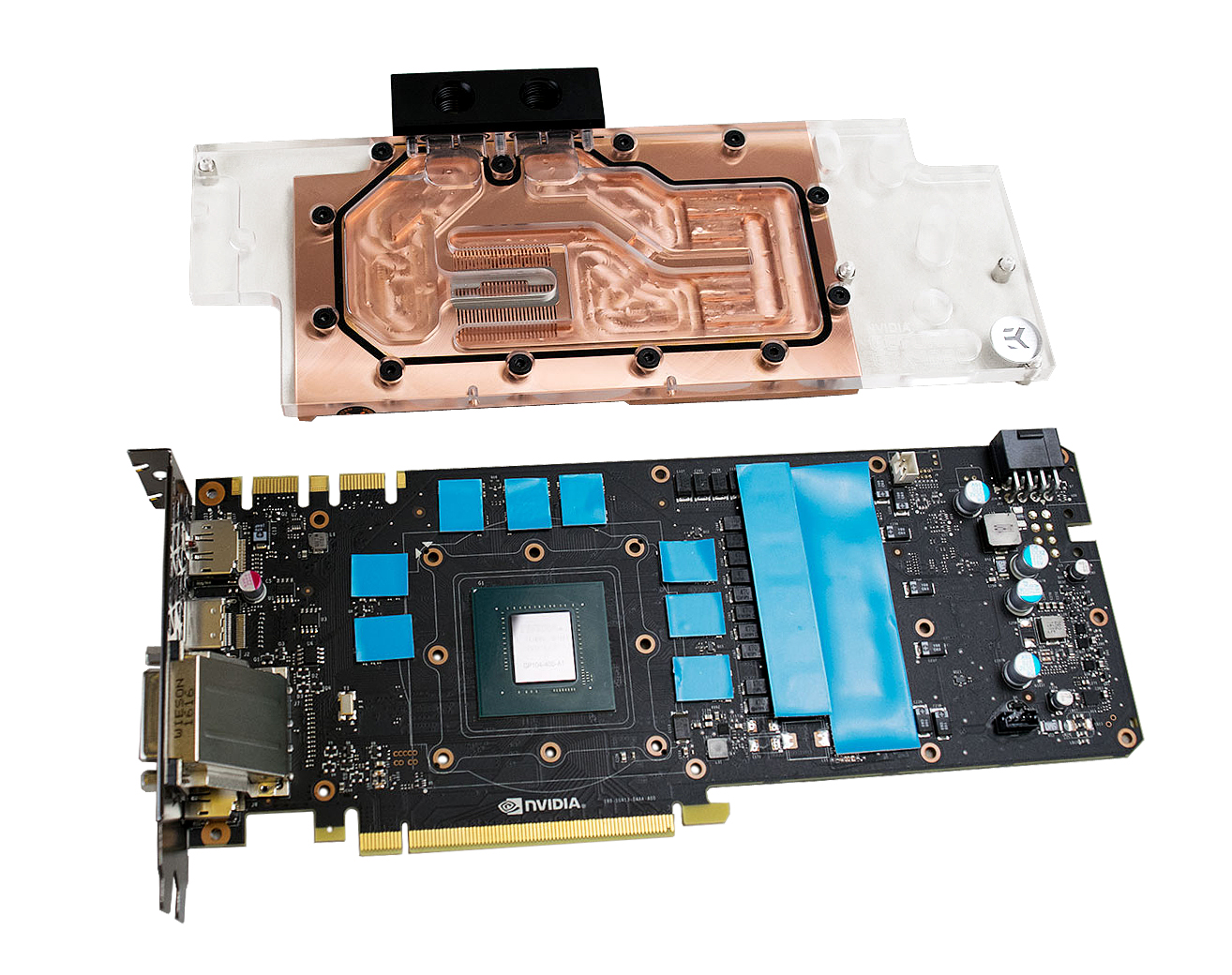
You’ll have to install the new thermal pads when the card is sufficiently clean and the isopropyl has dried up. EK Water Blocks provides the pads in the package, but you’ll need a pair of scissors to cut them down to the size of each memory chip. The VRMs and MOSFET thermal material doesn’t need to be cut into pieces, you can place long strips across all of them at once.
The next step is to add a liberal amount of thermal compound to the GPU surface. EK Water Blocks recommends using a plus and cross pattern that stretches across the GPU surface four times. Don’t worry about adding too much paste. You won’t cause any problems if there’s runoff beyond the die, provided that you use the supplied paste.
Block Placement
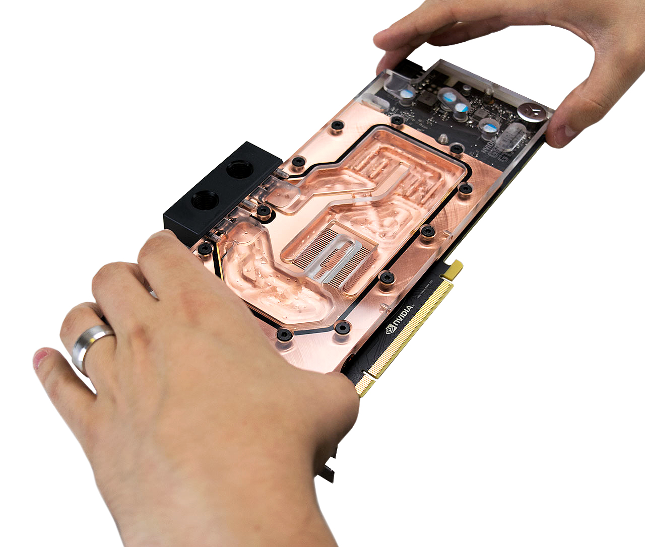
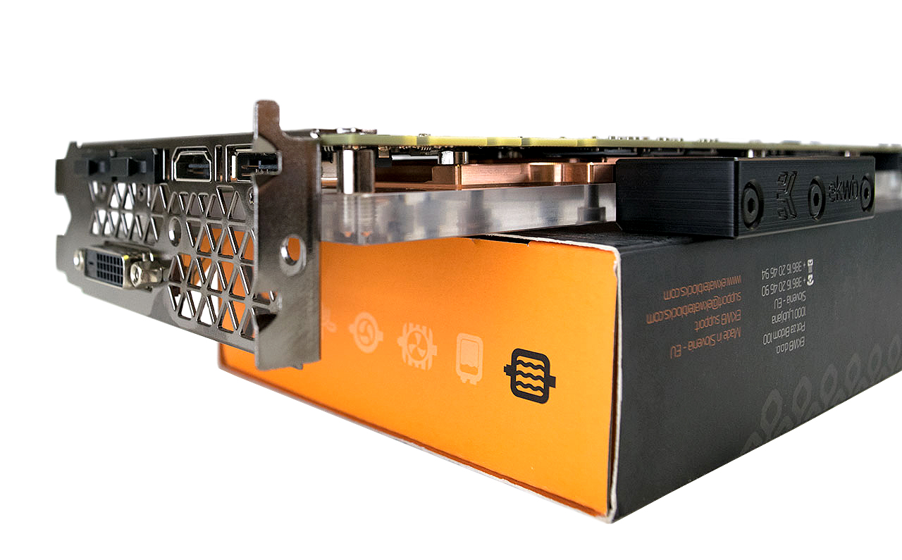
Now that the thermal paste and thermal pads are in place you can put the GPU block on the card. You’ll want to lower the block onto the PCB as level as possible so that the thermal paste spreads evenly. With the block resting on the graphics card circuit board, squeeze both parts firmly together and flip the card over. You’ll want to have some sort of raised surface so that the I/O bracket can hang off the side and the card can sit level. I find that the water block box acts as the perfect surface for this task.
EK Water Blocks proves all of the screws you need to install the block, but you’ll notice that there are more screws than you need. We suspect that the extra hardware is there so you can install the optional backplate because some of the extra screws are slightly longer.
To hold the block down, you’ll need 13 m2.5x6 AX1 screws, 13 PVC washers and one m2.5x6 screw. The larger screw holds the I/O bracket to the back of the card, and the 13 shorter screws hold the block into place. It’s important that you don’t use the wrong screws here. Copper is a very soft metal, and it can easily be damaged with too much force, or with a screw that is longer than the hole.
Hook It Up To The Loop
That’s really all it takes to install a GPU block on a GTX 1080 Founder’s Edition card. The only thing left to do is install it into your system by connecting the fittings, hooking up the tubing and filling the loop. Now you are ready for leak testing.
Follow Kevin Carbotte @pumcypuhoy. Follow us on Facebook, Google+, RSS, Twitter and YouTube.
Kevin Carbotte is a contributing writer for Tom's Hardware who primarily covers VR and AR hardware. He has been writing for us for more than four years.
-
kcarbotte Reply18230827 said:Don't forget to test the card BEFORE you install the water block
Yes, make sure the card is working first.
Also a good idea to get a baseline recording of temperatures and performance before and after. That wasn't an option to me as this wasn't my card and we were working with a limited time frame.
-
Math Geek it looks to me that if you removed the dvi output, this would be a single slot card. is that possible to do? i'm still working some future plans for a watercooled pc in my head and this struck me as a possible option. looking at the pictures, there is some kind of cover for it so can't see how it is attached to the card.Reply
so is it possible to remove the dvi output and only keep the 3 DP and single hdmi? would be easy to cut the bracket down if you can remove the output. -
uglyduckling81 "The VRMs and MOSFET thermal material doesn’t need to be cut into pieces, you can place long strips across all of them at once."Reply
No it was a choice he made. Not just lazy. It's not required. Probably should of read the article before commenting on the picture. -
iamacow Reply18231422 said:"The VRMs and MOSFET thermal material doesn’t need to be cut into pieces, you can place long strips across all of them at once."
No it was a choice he made. Not just lazy. It's not required. Probably should of read the article before commenting on the picture.
No need to read when pictures tell a thousand words. I've done my share of watercooled video cards, not once have i've seen the instructions say "don't worry about it, just throw the pads on for the best results" If you have it taken apart already, just spend 10 seconds and cut he pads to the right length. The best results would have been to cut the pads to the right size and than put some thermal paste (non conductive) on each mosfet for extra heat dissipation.
Its still a good article. It is hard to write an article, so either way good job :) -
uglyduckling81 Honestly it makes no difference what so ever.Reply
The idea is to ensure good complete contact between the item and the heat sink/block. It's the reason why you don't wan't too much paste between your CPU and heat sink. The object of the paste is to fill imperfections in the surfaces for full contact and maximum heat transfer. Whilst not increasing the distance between the CPU and block.
What happens in the dead space between the chips makes no difference.
I might agree with you if it was going to obstruct air flow but this is the point of water to replace moving air as it's more capable at moving heat away from the source. -
Ionlydothis Dumbest thing to do to this series since they don't Overclock any better on water and they're low heat cards anyway...Reply -
Olle_P "To clean the components, take your microfiber rag and pour some isopropyl onto it."Reply
This seems dangerous to me, in two ways:
1. Microfibre cloth is effective at collecting dust because it builds up a lot of static electricity. That static attracts dust and can/will of course also damage sensitive electronics.
2. Alcohol is highly flammable, so a spark between the electrically charged cloth and the surface could potentially start a fire.
I prefer to use tissue paper and Q-tips combined with isopropanol.
