Intel’s X-Lab: Tomorrow’s Network Happens Here
The Lightning Bolt
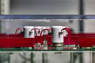
The IEEE formed an ad-hoc committee in 2001 to investigate cabling ESD, but the post-dot-com recession doomed the group’s efforts. The X-Lab’s current testing methods were salvaged from that aborted effort. Pete and company built a special cable discharge event tester called Thor (because Zeus was already taken by another machine) to replicate the type of shock that might manifest in a bad cable shock.
Actually, while Thor can charge up to 5000 V, air discharge arcs over at about 3000 V within a patch panel, leaving a maximum practical charge of 2000 V. That’s still enough to damage a server, switch ports, or other equipment. Results observed in a Thor discharge will show whether tested adapters will survive those shocks. Before our visit, I’d joked with the Intel team that it was always fun to watch stuff blow up. Pete remarked that this might be our chance.
Thor Strikes!
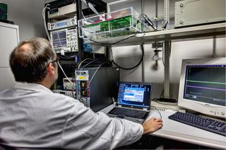
We installed a pair of wires into a patch panel and used current and voltage probes to measure the discharge. We cycled through three tests—500 V, 1000 V, and 2000 V—using an oscilloscope to record the data and channel it into Pete’s laptop, which he had me operate. “Be careful,” he warned me on my way to the bench, not really able to hide his smile. “We blew up a connection doing this not long ago.”
I won’t mislead you. Nothing blew up. I got to see some heavy duty spikes in the scope readings, but our connections and equipment remained intact. On my way to sit at the bench, however, I did crack my head pretty good on Thor’s bottom edge. Electrically safe, yes, but let the unwary beware.
The Rack Of Doom
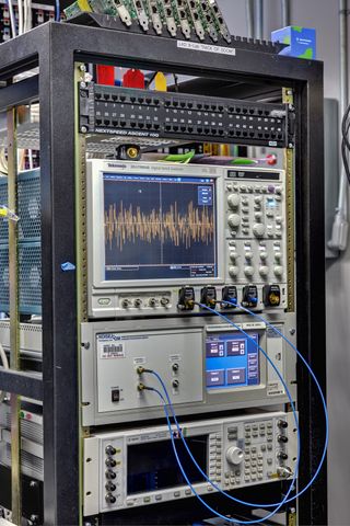
Where there’s transmitter conformance testing, expect similar treatment for receivers. For this pupose, the X-Lab has its so-called “Rack of Doom,” shown here. Tests using the equipment in this rack ensure that the receiver meets the receive error rate requirements defined in the IEEE Ethernet specification. For 10 Gb technologies (including 10GBASE-T), the IEEE defines a bit error ratio (BER) target of no more than one error in every 1012 bits received. That’s one error in every trillion bits. And if that’s not impressive enough, a 10 Gb receiver must perform with this same precision even when bombarded with various types of noise or when plugged into an erroneously wired connection, which isn’t uncommon in places where techs custom-cut their own cabling.
The Rack of Doom contains multiple random noise sources, some of which get used in alien crosstalk noise testing (see below). This ensures that the PHY’s internal digital signal processing (DSP) noise-cancelling systems function properly in the presence of noise that they don’t understand and therefore can’t cancel. In 10GBASE-T communications, this usually manifests as signals bleeding into the wire from adjacent cables in a cable tray.
Enter Noise
Data communications have three necessary components: a transmitter, a receiver, and something in between, even if that something is air (as in Wi-Fi). The medium is called a channel, and channels are partly defined in terms of electrical characteristics, including signal attenuation along the length of the channel. The longer the cable, the more power declines along its length. This is one problem with which the X-Lab has to grapple.
Stay On the Cutting Edge: Get the Tom's Hardware Newsletter
Get Tom's Hardware's best news and in-depth reviews, straight to your inbox.
Techs are also concerned about echo. Every interconnect point along the channel, such as a switch, creates something akin to a bump in the wire. At these points, part of the signal’s energy gets reflected back. In fluid dynamics, this would be like going from a big hose to a little hose and dealing with eddies and turbulence. The echoed signal returning to the transmitter distorts the main signal flow. Echo is one of several noise types that X-Lab staff must tackle. I was about to find that there were plenty more.
Six Around One
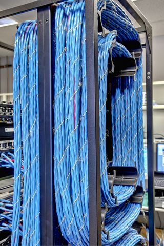
Pete noted, “Another thing that happens when you have multiple signals in a cable—and we have four signal pairs here—is crosstalk. This is when signals from one wire couple onto another wire. There are various forms of crosstalk. Within a cable, there are different levels of crosstalk, or XT, energy at the near end of the cable than the far end. We call that NEXT and FEXT. You can also get crosstalk from one cable to another—that’s the infamous alien crosstalk.
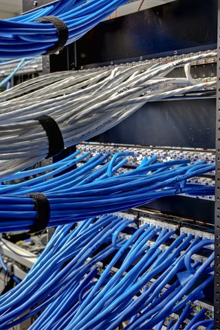
Alien crosstalk is noise introduced from an adjacent channel. One way we introduce that is to intentionally create a worst-case scenario. See the cables we’ve bundled and tightly wrapped around this rack? There’s a red cable in the bundle called the victim, and there are six aggressors, or disturbers, around it. We send traffic over the six pairs around the one. Colloquially, we call it a ‘six around one’ test. We try to couple as much alien energy into that cable in the center as possible and see how well we do. This isn’t designed in the IEEE standard, but it’s more of a real-world type test.”
Spendy Noise
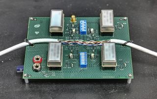
“Let’s take that noise problem one step further,” said Pete, drawing me over to a nearby bench to examine a small PCB with a dissected Ethernet cable tied across its middle. “Say we run these alien crosstalk tests. We see errors. The next thing we want is to see what energy is getting coupled in there. So you get an oscilloscope or spectrum analyzer or some piece of equipment to measure the noise on that center channel while these other guys are sending stuff. You can mathematically model that noise and define it in terms of some type of more standard noise source.
In the standard, the IEEE has defined a white Gaussian noise—think of it as random noise—that is flat across the frequency range from 10 to 400 MHz with a specific noise power of 141.9 dBm/Hz.” I raised an eyebrow at the specificity, and he shrugged. “Hey, I live with this and don’t get out much. But anyway, the IEEE says you want to grab four independent noise sources, which we have here, and couple those into each pair of the wire. While you have that noise coupled in, see how well you do. It’s like somebody’s yelling at you and you’re still trying to communicate.
We’ve got, in this case, one fixture that we’ve designed ourselves using some very precision noise sources that are quite spendy. How much? Each one of these little things is $2000. This is $8000 of noise here. We tend to think of things in terms of equivalent values here. ‘This is like a used car. That thing over there is like a house.’ With truly random noise, you cannot mathematically cancel it. Instead, you just have to figure out ways to deal with it.”
Whither The 1.21 Jigowatts?
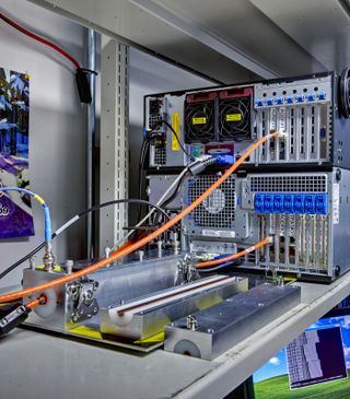
Those who have seen Back to the Future no doubt recall Doc and his revelation about the DeLorean’s “1.21 jigowatt” power requirements. Thankfully, we had neither plutonium nor lightning strikes present on our tour, but we did have a flux capacitor. That’s the cylindrical capacitor housed within the bisected metal block you see above. The data cable sets inside the center conductor, and it literally is in flux—hence the name. In electromagnetic field theory, there are lines of flux, so X-Lab engineers joke about it being the infamous “flux capacitor.” In reality, all capacitors are flux capacitors. Gotta love that geek humor. Anyway, the inserted cable has noise coupled onto all four of its wire pairs simultaneously.
Techs examine several signal types through the flux capacitor test to assess their effect on differential signaling, which assists with noise cancelation.
“Differential signaling is a very brute force method of noise cancellation,” explained Pete. “We split the signal, invert one half, run this split signal into a difference amplifier, and look at the resulting signal. If you have a signal that is common to both halves—meaning the same phase, polarity, and amplitude—coming into the receiver, the signals should cancel. Well, that’s great in math, but in the real world, one pair of wire will probably be a little longer or shorter than another, so you have an offset in time. They’ll probably be manufactured slightly differently, so the amplitude or power will be different. You subtract two things that are not identical but close. That’s why you get a little noise left over at the end.”
I asked if this was the same principle behind active noise cancelation in headphones.
“That’s a good way to think about it,” he said. “By the way, our alien crosstalk test uses a differential noise source. It comes in and stays there. For common-mode noise, we’re hoping that the system will work really well, the noise will balance, and be eliminated. But in the real world, it doesn’t always happen.”
(Note: For those who question the spelling of “jigowatts,” see http://www.imsdb.com/scripts/Back-to-the-Future.pdf at the famous shot 67.)
Cell Phones, Always Interrupting
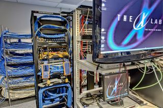
Many parts of the IEEE standard are “normative,” meaning they must be followed and adhered to. But a good manufacturer doesn’t want to merely meet spec; it wants to exceed it and see how far performance will go until the system breaks.
“For first-gen adapters, it wasn’t that hard to make them fail,” said Pete. “People would walk in with old 900 MHz cell phones and you’d see things drop in a heartbeat. That’s why we added this part called, oddly enough, the cell phone filter. It’s an additional passive filter network inserted between the magnetics module and the silicon chip. It’s inserted into the circuit to filter out those frequencies. So, with the first generation, we just put a passive filter on it. And it helped a lot. Otherwise, we wouldn’t have been able to ship a product.
“But additionally, you can design into algorithms the firmware to detect interfering radio signals and compensate for them, because you have walkie-talkies, cordless phones, and everything else. So the second-generation adapters included both the discrete cell phone filter and those algorithms. We’re continuing to raise the bar, too. I mean, what if someone wants to bring a radar system into the lab? OK, maybe that’s an exaggeration, but that’s the thought process. What are the potential scenarios? There are additional mechanisms I can’t even describe, because they’re proprietary, that enhance the noise immunity. But in the test environment, we have to crank up the volume of our disturbers to see where there’s the break.”
Power and noise immunity are “the last frontiers” for 10GBASE-T, and Pete proudly noted that their study and application is literally grounded in rocket science. Many of the principals and CTOs in the PHY companies with which Intel works have backgrounds in satellite communications. That’s where much of the theory behind 10GBASE-T technology has its roots.
“Those algorithms are how we hear a whisper in a thermonuclear explosion,” Pete added. “And hey! We have alien crosstalk. That’s where the aliens meet our rocket science!”
From Aliens To Robots
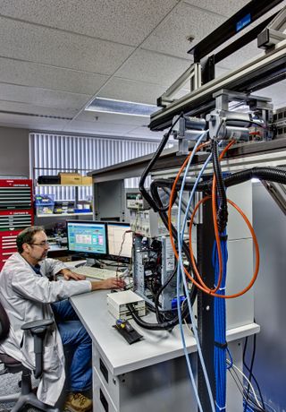
As mentioned earlier, the bit error ratio target for 10GBASE-T is one in one trillion bits. Confirming that rate (or better) requires multiple kinds of tests, but the X-Lab’s standard test pass involves 500 million packets using 1518-byte frames transmitted for approximately 15 minutes. One hundred of these test passes then comprise a single test trial, and there are many such trials during a product test cycle.
“The reason we do that—thousands of link attempts and hundreds of millions of packets—is that 10GBASE-T is a huge math problem that has to be solved in real-time,” said Pete. “You don’t always get the same answer, because it’s non-deterministic. Because of that non-determinism, you really want to do a lot of trials to make sure that the system is converging consistently over these different math problems. Note than the full test trial is executed on one cable type from one manufacturer on a two-meter length…then on a four-meter, on a seven, on a 20, on a 55, on a 90, and on a 100-meter channel. Finally, the entire set is repeated with different manufacturers. You can see that we easily end up transmitting trillions of packets during the qualification phase.”
To enable the kind of 24x7 testing necessary when pushing all of those packets during a product test cycle, the Intel team has developed several robotic solutions to automatically configure test channels. One of these is a third-generation robot called Patch that was two years in the making. If you’re expecting Johnny 5 or Asimo, you might be a bit disappointed, but Patch is still pretty freaking cool up close.
Patch is about six feet tall and three feet wide, comprised mainly of a frame, a LAN jack patch panel, and a couple of plugging/unplugging devices that slide along a shelf in front of that panel. Patch is tethered to a control PC and tasked with plugging and unplugging network cables from its patch panel…over…and over.
Patch And Ports
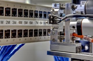
Randy Kumenius, the engineer who designed much of Patch and often operates it, described the robot as “a two-axis robotic solution based on a four-axis National Instruments motion card. Both axes are closed-loop servo motors. We drive an analog voltage out to the motor, which sends back a four-bit encoder. We get 4096 counts per revolution because of the four-line encoder. So we can get very precise positioning. And it’s absolute positioning information, so once this one’s home and the next one’s home, we zero that and all of the ports are X amount of counts from zero.”
Patch can handle two cables of any length simultaneously, helping to double its potential work output and increase efficiency. Testers can analyze PHY communications in any length from one to 100 meters in one-meter increments. Patch has proven so useful and reliable as part of Intel’s Oregon site’s that its offspring will be deployed to multiple platform test locations in 2011.
-
super_tycoon dogman_1234Anyone else notice the Guy Fawkes mask in the background?Reply
It's existence is noted in the text for pic3, though I can only wonder why he has it. Is it good taste to associate yourself with 4chan and anon nowadays? -
gmoney86 I am not sure if I ever saw the sign to the X-Lab when working at Jones Farm, but I did always wonder what went on in the labs that were similar to it. They kind of looked like IT work rooms to me, though it makes sense to have a need for oscilloscopes, soldering irons, networking tools, etc. for certain R&D projects.Reply -
scook9 Awesome article, I just finished me BSEE degree and now work in an network company where I help engineer servers so this is right up my alley!Reply -
This all started in 1990 with the creation of EtherExpress 16 by a handful of people led by a visionary leader, Steve Kassel.Reply
-
williamvw super_tycoonIt's existence is noted in the text for pic3, though I can only wonder why he has it. Is it good taste to associate yourself with 4chan and anon nowadays?My guess is that it was just a fun-looking mask someone had brought to the lab, perhaps because they also enjoyed "V for Vendetta." (I did!) I'd wager that the X-Lab crew had no idea of the mask's fleeting association with 4chan's anti-Scientology protests, much less the religious motivations behind Fawkes's attempted regicide. Let's not accuse good people without cause.Reply -
chovav Excellent article Tom (Willam actually). Nice reading, informative and geeky, just the way I like it. Amazing to see that they transfer 76TB in just one test (500,000,000*1518*100). Good job!Reply -
williamvw chovavExcellent article Tom (Willam actually). Nice reading, informative and geeky, just the way I like it. Amazing to see that they transfer 76TB in just one test (500,000,000*1518*100). Good job!Yeah, I was stunned. I honestly expected some automated tests, maybe a few guys with scopes taking occasional signal readings -- NOTHING like what I saw. I'd assumed that a technology as old as Ethernet was pretty much a done deal and didn't require much hand holding at this point. I couldn't have been more wrong.Reply
Most Popular


